![[Home]](../iconz/home.gif) Return to Home Page
Return to Home Page
Application Note # C35
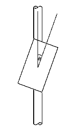
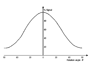
While investigating reinforcement in concrete, you will have been making good use of the directional properties of the CoverMaster search head, whereby the search head gives the maximum signal when the long axis of the head is aligned parallel to the reinforcing bar, and gives a minimum signal when the head is at right angles (which is what the word "orthogonal" means).
You may have noticed that, if it is a small diameter bar, the signal decreases rapidly as you rotate the search head away from alignment, and practically disappears when the head is at right angles; but if it is a large diameter bar, the signal only reduces slightly as you rotate the head, and may still be at about half-strength when at right angles. You may even have noticed that this effect is true regardless of the depth of cover to the reinforcing bar.
This new bar-sizing method simply formalises and quantifies this phenomenon, so that you can accurately determine the diameter of a bar of unknown size (after which you can use the CoverMaster in the usual way to determine the cover to a bar of now known size).

|
|

|
| Head Alignment |
|
Variation of signal with head angle |
(Full details of the method are given in "Improvements to the Orthogonal Method for Determining Reinforcing Bar Diameter using a Cover Meter" published in the Conference Proceedings "Extending the Life of Bridges, Civil & Building Structures", Structural Faults & Repair, London, July 1995; the Abstract is on this site, and reprints are available from Protovale as paper P95).
It is important to first map out the position of all the bars, and chalk their positions on the concrete surface, by using the CoverMaster in the usual way, with MODE at either LOCate or +aud.
You can then pick a spot to measure a bar where you know there are no other bars in the immediate vicinity which might upset the readings.
Please note that the method, and the table beside it, are only suitable for measurements taken using the standard (larger) search head.
- Now just follow these steps:
- [1] Set the MODE knob to CALib (as if to zero the instrument).
- [2] It doesn't really matter where you set the DIAM knob; but if the bar is suspected to be either quite small or rather deep, set it to a smallish diameter; conversely if the bar is suspected to be either rather large or quite shallow, set it to a largish diameter.
- [3] With the head well away from metal, use the ZERO knob to bring the meter to centre and the display to ±.000v.
- Leave the MODE knob at CALib.
- [4] Place the search head exactly over the bar and parallel to it, adjusting the head position as necessary to get the maximum possible reading.
- (If the reading is greater than +1.900v, or the display shows a single digit 1 at the left of an otherwise blank screen, the signal is too strong: turn the DIAM knob clockwise until a reasonable reading is obtained, and then re-zero from step [3].)
- Write this "parallel" reading down.
- [5] Now rotate the search head by 90° to be at right angles to the bar, but still centrally over it; this time you are looking for the minimum possible signal.
- (If the reading is less than about +.015v, the signal may be too weak for a reliable answer: if this is the case, turn the DIAM knob anticlockwise until you get sufficient signal, and repeat steps [3], [4] and [5].)
- Write this "orthogonal" reading down.
- [6] Divide the (smaller) orthogonal reading by the (larger) parallel reading to get a ratio between about 0.04 and 0.50.
- [7] Consult the table at right: your ratio will fall between two numbers in the left-hand column; and the bar diameter corresponding to a ratio falling within that band is shown in the right-hand column.
|
| < | 5 |
| .035 |
|
| | 6 |
| .050 |
|
| | 7 |
| .066 |
|
| | 8 |
| .078 |
|
| | 10 |
| .102 |
|
| | 12 |
| .135 |
|
| | 14 |
| .160 |
|
| | 16 |
| .180 |
|
| | 18 |
| .190 |
|
| | 20 |
| .210 |
|
| | 22 |
| .220 |
|
| | 25 |
| .260 |
|
| | 28 |
| .340 |
|
| | 32 |
| .415 |
|
| | 40 |
| .500 |
|
| > | 50 |
|
That's all there is to it: you now know the bar diameter, and can measure the cover in the usual way by setting the DIAM knob to that size, re-zeroing the instrument (on CALib), and measuring the cover (on DEPth or +aud) with the head re-aligned parallel to the bar.
Example
(Actual measurement of a T12 bar at 40mm cover with DIAM at 16):
Parallel reading = +.292v, orthogonal reading = +.033v; ratio = 33÷292 = .113.
This lies between .102 and .135 in the table, so the bar diameter is 12mm.
Precautions
If the head is not aligned exactly during the taking either of the two readings, the ratio will always be more than the correct value, so the method will always over-estimate the bar diameter. So, if your deduced diameter comes out to be one of the "half-sizes" - for example 22mm - but you know that no such size was used in the concrete reinforcement, you should assume that this is an over-estimate of the size of - in this example - 20mm diameter bar.
For reliable results, the nearest neighbouring bar should be more than 100mm away. Neighbouring parallel bars at 100mm distance or less will always result in a progressive over-estimate of diameter; transverse bars at less than 75mm distance (150mm pitch) produce unpredictable results.
 Up to to of page
![[Home]](../iconz/home.gif) Return to Home Page . . . . . .
Back to "Technical Library" page
. . . . . . Link to CoverMaster CM52
Return to Home Page . . . . . .
Back to "Technical Library" page
. . . . . . Link to CoverMaster CM52
Copyright © Protovale 1995, 1999


![]() Return to Home Page . . . . . .
Back to "Technical Library" page
. . . . . . Link to CoverMaster CM52
Return to Home Page . . . . . .
Back to "Technical Library" page
. . . . . . Link to CoverMaster CM52